ELTECHMASH offers a new-generation industrial electron-beam Installation for electron-beam phisical vapor deposition of single-layer and multi-layer metallic, oxide, carbide or boride coatings on various articles, partly on turbine blades.
Technical parameters of the Plant
| Parameter Description | Value |
|
Size of cassette holder with workpieces, mm, no more than: - diameter- length |
250 |
| Speed of workpiece rotation on horizontal shaft, rpm | 1-25 |
| Number of crucibles, pcs. | 4 |
| Crucible inner diameter, mm | 70 |
| Max. Length of evaporated ingots, mm | 500 |
| Ingot feed rate, mm/minute | 0,5 - 350 |
|
Distance from crucible upper edge to cassette holder axis of rotation or to plane of deposition, mm |
350 |
| Quantity and rated power of EB guns, n x kW: - for evaporation of material out of crucibles - for heating of workpieces Type of electronic guns: gas-discharge cold-cathode guns |
4х100 |
| Power consumption, kW, no more than |
300 |
| Rated accelerating voltage, kV | 30 |
| Operating vacuum inside chambers, Pa (mm Hg) | 6х10-3 - 1х10-2 (5х10-5 - 1х10-4) |
| Rated three-phase 50 Hz AC mains voltage, V | 380 |
| Plant outer dimensions, mm: - length - width - height |
10850 |
| Weight of plant, ton, no more than | 25 |
In terms of design, this plant features electron-beam heaters with cold cathode. A cold cathode made of aluminium excludes any deformation, thus yielding a stable electron beam with cathode life up to 1000 hours.
On the other hand, electron-beam cold-cathode heaters are able to function in the vacuum of 5x10⁻¹ Pa, whereas electron-beam hot ribbon-type cathode heaters cannot function in the vacuum lower than 5x10⁻² Pa.
The use of electron-beam cold-cathode heaters involves inflow of oxygen into zirconium dioxide vapour cloud and makes it possible to generate a stoichiometric layer of protective coating. The plant consists of a unit of vacuum chambers with mechanisms, devices and systems, which ensure running of the process of electron-beam coating deposition, in the vacuum environment, on various articles. The lower flange of the process chamber adjoins the crucible unit comprising four copper water-cooled crucibles and four feeder mechanisms for ingots to be evaporated. Ingots of the evaporable material are loaded into the said mechanisms from above through the crucibles. Four electron-beam cold-cathode guns are used to evaporate the materials out of the crucibles and are installed in such a way that each electronic gun intended to evaporate an ingot in the corresponding crucible can also be used to evaporate the material from the neighbouring crucible. This may be necessary in case of re-arrangement or changing the quantity of crucibles in line with the process requirements.
Two electronic guns atop the process chamber are used to heat up workpieces. Two synchronized dampers are intended for screening of workpieces during pre-heating of the evaporable materials and workpieces until the process has become stable. Two air-lock chambers are used to reload the workpieces to be coated. The volume of the process chamber and that of the air-lick chamber is separated by two gate valves. The air-lock chambers contain devices for ionic cleaning of workpieces prior to coating. Availability of two auxiliary chambers increases the plant efficiency. Coating on workpieces fed sequentially from the air-lock chambers is applied without loss of vacuum in the evaporation chamber. The horizontal feeder mechanism serves to move workpieces from the air-lock chambers into the evaporation chamber and back, as well as to turn workpieces over. To compensate any potential bending of the shaft in its extreme extended position, the shaft is provided with a front journal support.
The design of the shaft lead-in point into the chamber provides tightness of the shaft linear motion and tightness of the shaft rotary motion with different seals. Such separation prevents premature aging of the cup-type seal used for the shaft linear motion. The shafts are provided with current collectors to pick up the signals coming from the thermocouples attached to the cassette holder with blades. The mounting fixture with a workpiece is secured onto the free end of the shaft and can be cooled, where necessary, with water running from the shaft.
Electron Beam Gun Power Supply Units
The plant is provided with a power supply unit with the accelerating voltage of 30 kV per electronic gun. Power supply of each electron gun from a separate source allows more stable provide the technological process.
Control System.
The control system ensures:
- monitoring of the technical condition of all plant systems;
- pre-start automated preparation of the plant for the process;
- control of the plant mechanisms from the operator’s control panel in the course of the process running;
- on-line collection, processing, displaying and storage of the process parameters and the process history.
|
|
|
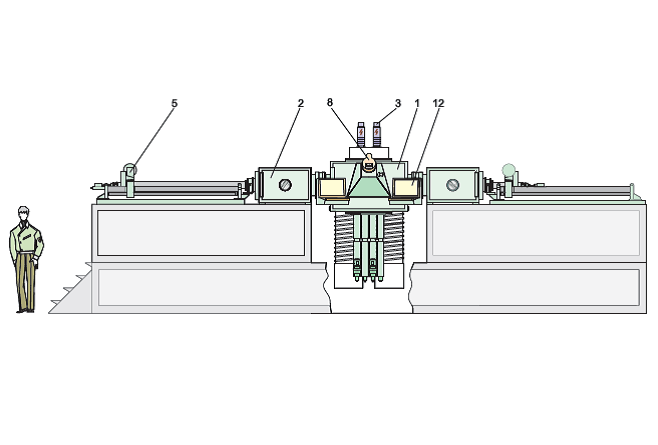
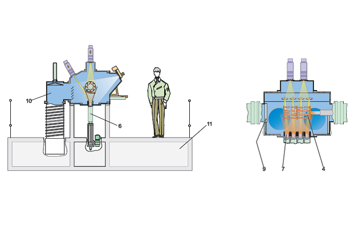
1. Process chamber 2. Air-lock chamber 3. Electronic gun 4. Cassette holder 5. Cassette holder (workpiece) feeder mechanism 6. Ingot feeder mechanism |
7. Crucible 8. Viewing system 9. Damper 10. Vacuum system 11. Maintenance platform 12. Control panel |
|
|
|